Общий каталог Mitsubishi 2020 - 2021 - страница 631
Навигация
 Каталог Mitsubishi Materials запасные части
 Каталог Mitsubishi Materials резьбонарезной инструмент
 Каталог Mitsubishi Materials СНП с CBN и PCD для токарной обработки
 Каталог Mitsubishi Materials сверлильные инструменты
 Каталог Mitsubishi Materials расточной инструмент
 Каталог Mitsubishi Materials пластины для точения
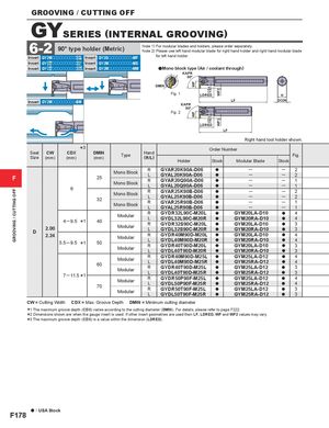
GROOVING / CUTTING OFF WFWF CDXCDX WF2WF2 GROOVING / CUTTING OFF GYSERIES (INTERNAL GROOVING) 6-2 90° type holder (Metric) Note 1) For modular blades and holders, please order separately.Note 2) Please use left hand modular blade for right hand holder and right hand modular blade Insert GY2Mooooooooo--G GSM Insert GY2Gooooooooo-MF for left hand holder. Insert GY22M G ooooooooo--G GUL Insert GY2Mooooooooo-MS Insert GY11M G ooooooooo--G GFMGS Insert GY2Mooooooooo-MM aMono block type (Air / coolant through) KAPR 90° DMIN Fig. 1 LDRED H Insert GY2Mooooooooo-BM LF DCONKAPR 90° Fig. 2 LDRED LF Right hand tool holder shown. Seat CW CDX *3 DMINSize(mm)(mm)(mm)TypeHand(R/L) Order Number Fig.HolderStockModular BladeStock F 6 25 Mono Block RL GYAR20K90A-D06GYAL20K90A-D06Mono BlockRLGYAR20Q90A-D06GYAL20Q90A-D06aaaa32Mono BlockRLGYAR25K90B-D06GYAL25K90B-D06Mono BlockRLGYAR25R90B-D06GYAL25R90B-D06aaaa──────── ─ 2─2─1─1─2─2─1─1 4 ─ 9.5 *1 40D2.002.245.5 ─ 9.5*150ModularRGYDR32L90C-M20L aLGYDL32L90C-M20RaModularRGYDR32S90C-M20LaLGYDL32S90C-M20RaModularRGYDR40M90D-M20LaLGYDL40M90D-M20RaModularRGYDR40T90D-M20LaLGYDL40T90D-M20RaGYM20LA-D10 a 4GYM20RA-D10a4GYM20LA-D10a3GYM20RA-D10a3GYM20LA-D10a4GYM20RA-D10a4GYM20LA-D10a3GYM20RA-D10a3 607 ─ 11.5 *170ModularR GYDR40M90D-M25L aLGYDL40M90D-M25RaModularRGYDR40T90D-M25LaLGYDL40T90D-M25RaModularRGYDR50P90F-M25LaLGYDL50P90F-M25RaModularRGYDR50T90F-M25LaLGYDL50T90F-M25RaGYM25LA-D12 a 4GYM25RA-D12a4GYM25LA-D12a3GYM25RA-D12a3GYM25LA-D12a4GYM25RA-D12a4GYM25LA-D12a3GYM25RA-D12a3 CW = Cutting Width CDX = Max. Groove Depth DMIN = Minimum cutting diameter ***123 The maximum groove depth (CDX) varies according to the cutting diameter (DMIN). Dimensions shown are when the gauge insert is used. If other insert geometries are The maximum groove depth (CDX) is a value within the dimension (LDRED). For details, please refer to page used then LF, LDRED, WF and F222. WF2 values may vary. a : USA Stock F178