Общий каталог Mitsubishi 2020 - 2021 - страница 491
Навигация
 Каталог Mitsubishi Materials запасные части
 Каталог Mitsubishi Materials резьбонарезной инструмент
 Каталог Mitsubishi Materials СНП с CBN и PCD для токарной обработки
 Каталог Mitsubishi Materials сверлильные инструменты
 Каталог Mitsubishi Materials расточной инструмент
 Каталог Mitsubishi Materials пластины для точения
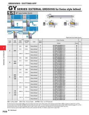
GROOVING / CUTTING OFF 0HF CW HBH H HF B H GROOVING / CUTTING OFF GYSERIES (EXTERNAL GROOVING for Swiss style lathes) 1-1 00° type holder (Inch) CDX Insert GY2Mooooooooo--G GSM Insert GY2Gooooooooo-MF Insert GY22M G ooooooooo--G GUL Insert GY2Mooooooooo-MS Insert GY11M G ooooooooo--G GFMGS Insert GY2Mooooooooo-MM LF LH Fig. 1 LHCUTDIA Fig. 2 CUTDIA LH 2 LH 2 Insert GY2Mooooooooo-BM Insert GY2Mooooooooo--G GSM Insert GY22M G ooooooooo--G GUL Insert GY2MoooooR/Loo-GM Right hand tool holder shown. Seat CW *4CDX CUTDIASize(inch)(inch)(inch)TypeHand(R/L) Order Number Fig.HolderStock F .433 .866 Mono Block RLC.059.5121.024Mono BlockMono Block.669 *11.338 *2Mono BlockRLRLRLGYSRUS06B00-C11 a 1GYSLUS06B00-C11a1GYSRUS08B00-C13a2GYSLUS08B00-C13a2GYSRUS10B00-C17a2GYSLUS10B00-C17a2GYSRUS12B00-C17a2GYSLUS12B00-C17a2 .433 .866 Mono Block RL GYSRUS06B00-D11 a 1GYSLUS06B00-D11a1 D .079 .512 1.024 Mono Block RL.088Mono Block.669 *11.338 *2Mono BlockRLRLGYSRUS08B00-D13 a 2GYSLUS08B00-D13a2GYSRUS10B00-D17a2GYSLUS10B00-D17a2GYSRUS12B00-D17a2GYSLUS12B00-D17a2 .433 .866 Mono Block RL GYSRUS06B00-E11 a 1GYSLUS06B00-E11a1 .512 1.024 Mono Block RL GYSRUS08B00-E13 a 2GYSLUS08B00-E13a2 E .094.098.108 Mono Block.669 *11.338 *2Mono BlockRLRL GYSRUS10B00-E17 a 2GYSLUS10B00-E17a2GYSRUS12B00-E17a2GYSLUS12B00-E17a2 Mono Block.787 *11.574 *2Mono BlockRLRL GYSRUS10B00-E20 a 2GYSLUS10B00-E20a2GYSRUS12B00-E20a2GYSLUS12B00-E20a2 .512 1.024 Mono Block RL GYSRUS08B00-F13 a 2GYSLUS08B00-F13a2 F .118.125 Mono Block.669 *11.338 *2Mono BlockRLRL GYSRUS10B00-F17 a 2GYSLUS10B00-F17a2GYSRUS12B00-F17a2GYSLUS12B00-F17a2 .128 Mono Block.787 *11.574 *2Mono BlockRLRL GYSRUS10B00-F20 a 2GYSLUS10B00-F20a2GYSRUS12B00-F20a2GYSLUS12B00-F20a2 CW = Cutting Width CDX = Max. Groove Depth CUTDIA = Max. Cut Off Diameter ****1234 The maximum groove depth (CDX) varies according to the insert used. Please refer to the maximum groove depth (CDX) of inserts on pages F011 to F015. The maximum cut off diameter (CUTDIA) varies according to the insert used. The cut off diameter is double the maximum groove depth (CDX) of inserts on pages F011 to F015. Dimensions shown are when the gauge insert is used. If other insert geometries are used then LF, LH and LH 2 values may vary. The maximum groove depth (CDX) is limited by the workpiece diameter. For details, please refer to page F208. a : USA Stock F038