Общий каталог Mitsubishi 2020 - 2021 - страница 240
Навигация
 Каталог Mitsubishi Materials запасные части
 Каталог Mitsubishi Materials резьбонарезной инструмент
 Каталог Mitsubishi Materials СНП с CBN и PCD для токарной обработки
 Каталог Mitsubishi Materials сверлильные инструменты
 Каталог Mitsubishi Materials расточной инструмент
 Каталог Mitsubishi Materials пластины для точения
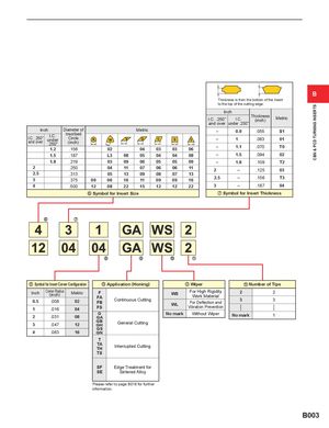
CBN & PCD TURNING INSERTS B Thickness is from the bottom of the insert to the top of the cutting edge. Inch I.C. .250"and overI.C.under .250"Thickness(inch)Metric Inch Diameter ofI.C. .250"and overI.C.under.250"InscribedCircle(inch)1.2.15602Metric – 0.9 .055 S1–1.0630104030306–1.1.070T0 1.5 .187 L3 08 05 04 04 08 – 1.5 .094 02 1.8 .219 03 09 06 05 05 09 – 1.8 .109 T2 2 .250 04 11 07 06 06 11 2 – .125 03 2.5 .313 05 13 09 08 07 13 3 .375 09 06 16 11 09 09 16 2.5 – .156 T3 4 .500 12 08 22 15 12 12 22 3 – .187 04 n Symbol for Insert Size m Symbol for Insert Thickness , Symbol for Insert Corner Configuration . Application (Honing) / Wiper Number of Tips Inch Corner Radius(inch)Metric0.5.00802FFAFB Continuous Cutting1.01604FS WS For High RigidityWork Material2WLFor Deflection andVibration Prevention323 G2.03108GA No mark Without Wiper No mark 1 3 .047 12 GBGH General Cutting GS 4 .063 16 GN T TATH Interrupted Cutting TS SF Edge Treatment for SE Sintered Alloy Please refer to page B016 for further information. B003