Общий каталог Mitsubishi 2020 - 2021 - страница 1736
Навигация
 Каталог Mitsubishi Materials запасные части
 Каталог Mitsubishi Materials резьбонарезной инструмент
 Каталог Mitsubishi Materials СНП с CBN и PCD для токарной обработки
 Каталог Mitsubishi Materials сверлильные инструменты
 Каталог Mitsubishi Materials расточной инструмент
 Каталог Mitsubishi Materials пластины для точения
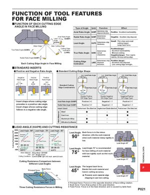
FUNCTION OF TOOL FEATURES FOR FACE MILLING yFUNCTION OF EACH CUTTING EDGE ANGLE IN FACE MILLING Type of Angle Symbol Function Effect Axial Rake Angle GAMP Determines chipdisposal direction.Positive : Excellent machinability. Axial Rake AngleLead(GAMP) Radial Rake Angle GAMF Determinessharpness. Negative : Excellent chip disposal. Wiper Edge Angle(KAPR)Main Cutting Edge Lead Angle KAPR Determines chipthickness. Small : Thin chips and smallcutting impact.Large back force. Cutting Edge Positive(large) : True Rake Angle (GAMO) Inclination Determines Excellent machinability. (LAMS) True Rake Angle GAMO actual Minimal welding. sharpness. Negative(large) : Poor machi- Radial Rake Angle (GAMF) nability. Strong cutting edge. Each Cutting Edge Angle in Face Milling Cutting EdgeInclination Determines chip Positive (large) :LAMSdisposalExcellent chip disposal.direction.Low cutting edge strength. ySTANDARD INSERTS a Positive and Negative Rake Angle a Standard Cutting Edge Shape Axial Rake Angle Axial Rake Angle Axial Rake Angle Negative Neutral Positive Rake Angle Rake Angle Rake Angle Standard Cutting Edge Combinations Radial Rake Angle Radial Rake Angle Radial Rake Angle Double Positive Double Negative Negative/Positive (DP Edge Type) (DN Edge Type) (NP Edge Type) · Insert shape whose cutting edge Axial Rake Angle (GAMP) Positive ( + ) Negative ( – ) Positive ( + ) precedes is a positive rake angle. Radial Rake Angel (GAMF) Positive ( + ) Negative ( – ) Negative ( – ) · Insert shape whose cutting edgefollows is a negative rake angle.Insert Used Positive Insert (One Sided Use) Negative Insert (Double Sided Use) Positive Insert (One Sided Use) Steel a ─ a Cast Iron ─ a a Aluminum Alloy a ─ ─ Difficult-to-Cut Material a ─ a y LEAD ANGLE (KAPR) AND CUTTING RESISTANCE Lead Angle : 90° Lead Angle : 75° Lead Angle : 45° Lead Angle Back force is in the minus Principal Principal PrincipalForceForceForce 90° direction. Lifts the work materialwhen work material clamp rigidity is Feed Force Feed Force Feed Force low. Lead Angle 90° Back Force Back Force Back Force Lead Angle Lead Angle 75° is recommended fz(IPT) fz(IPT) fz(IPT)Work Material :Alloy Steel(281HB)Tool : ø4"Single Insert75°for face milling of work materialwith low rigidity such as thin work Cutting Conditions : vc=410 SFM ap=.157 inch ae=4.33 inch material. Lead Angle 75° Cutting Resistance Comparison between Different Lead Angles Lead Angle The largest back force.Back ForcePrincipal Force45°Bends thin work material andlowers cutting accuracy. P Feed Force ae * Prevents chipping work material edge in cast iron cutting. Lead Angle 45° ap Table FeedThree Cutting Resistance Forces in Milling*** Principal force: Force is in the opposite direction of face Back force: Force that pushes in the axial direction. Feed Force: Force is in the feed direction and is caused milling rotation. by table feed. P021 Cutting Resistance (N) Work Material TECHNICAL DATA