Общий каталог Mitsubishi 2020 - 2021 - страница 1734
Навигация
 Каталог Mitsubishi Materials запасные части
 Каталог Mitsubishi Materials резьбонарезной инструмент
 Каталог Mitsubishi Materials СНП с CBN и PCD для токарной обработки
 Каталог Mitsubishi Materials сверлильные инструменты
 Каталог Mitsubishi Materials расточной инструмент
 Каталог Mitsubishi Materials пластины для точения
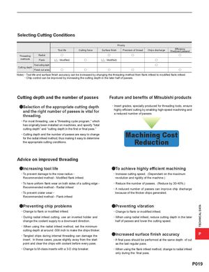
Selecting Cutting Conditions Priority Tool life Cutting force Surface finish Precision of thread Chips discharge (RedEufcfiecdiepnacysses) Threading Radial u u u u methods Flank (] : Modified) u (] : Modified) u Fixed cutting depth u Cutting depth Fixed cut area u u u u u Note) · Tool life and surface finish accuracy can be increased by changing the threading method from flank infeed to modified flank infeed. · Chip control can be improved by increasing the cutting depth in the later half of passes. Cutting depth and the number of passes Feature and benefits of Mitsubishi products aSelection of the appropriate cutting depth · Insert grades, specially produced for threading tools, ensure and the right number of passes is vital forthreading. highly efficient cutting by enabling high-speed machining anda reduced number of passes. · For most threading, use a "threading cycle program," which has originally been installed on machines, and specify "total cutting depth" and "cutting depth in the first or final pass." · Cutting depth and the number of passes are easy to changefor the radial infeed method, thus making it easy to determineMachining Cost the appropriate cutting conditions. Reduction Advice on improved threading aIncreasing tool life aTo achieve highly efficient machining · To prevent damage to the nose radius - · Increase cutting speed. (Dependant on the maximum Recommended method - Modified flank infeed. revolution and rigidity of the machine.) · To have uniform flank wear on both sides of a cutting edge - · Reduce the number of passes. (Reduce by 30-40%.) Recommended method - Radial infeed · A reduced number of passes can improve chip discharge · To prevent crater wear - because of the thicker chips generated. Recommended method - Flank infeed aPreventing chip problems aPreventing vibration · Change to flank or modified infeed. · Change to flank or modified infeed. · During radial infeed cutting, use an inverted holder and · When using radial infeed, reduce cutting depth in the later change the coolant supply to a downward direction. half of passes and lower the cutting speed. · When using the radial infeed method, set the minimum cutting depth at around .008 inch to make the chips thicker. · Tangled chips during internal threading can damage the aIncreased surface finish accuracy P insert. In these cases, pause slightly away from the start · A final pass should be performed at the same depth of cut point and clear the chips with coolant before every pass. as the last regular pass. · Change to M-class inserts with a 3-D chip breaker. · When using the flank infeed method, change to radial infeed only during the final pass. P019 TECHNICAL DATA