Общий каталог Mitsubishi 2020 - 2021 - страница 1668
Навигация
 Каталог Mitsubishi Materials запасные части
 Каталог Mitsubishi Materials резьбонарезной инструмент
 Каталог Mitsubishi Materials СНП с CBN и PCD для токарной обработки
 Каталог Mitsubishi Materials сверлильные инструменты
 Каталог Mitsubishi Materials расточной инструмент
 Каталог Mitsubishi Materials пластины для точения
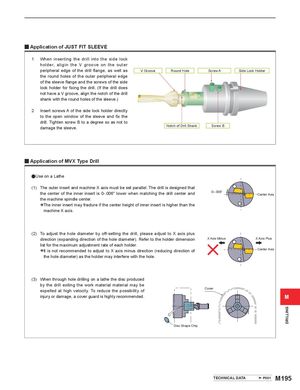
y Application of JUST FIT SLEEVE 1 When inserting the drill into the side lock holder, aligin the V groove on the outer peripheral edge of the drill flange, as well as V Groove Round Hole Screw A Side Lock Holder the round holes of the outer peripheral edge of the sleeve flange and the screws of the side lock holder for fixing the drill. (If the drill does not have a V groove, align the notch of the drill shank with the round holes of the sleeve.) 2 Insert screws A of the side lock holder directly to the open window of the sleeve and fix the drill. Tighten screw B to a degree so as not to damage the sleeve. Notch of Drill Shank Screw B y Application of MVX Type Drill aUse on a Lathe (1) The outer insert and machine X axis must be set parallel. The drill is designed that the center of the inner insert is 0-.006" lower when matching the drill center and 0‒.006" Center Axis the machine spindle center. *The inner insert machine X axis. may fracture if the center height of inner insert is higher than the (2) To adjust the hole diameter by off-setting the drill, please adjust to X axis plus direction (expanding direction of the hole diameter). Refer to the holder dimension X Axis Minus X Axis Plus list for the maximum adjustment rate of each holder. *It is the not hole recommended to adjust to X axis minus direction (reducing diameter) as the holder may interfere with the hole. direction of Center Axis (3) When through hole drilling on a lathe the disc produced by the drill exiting the work material material may be expelled at high velocity. To reduce the possibility of Cover injury or damage, a cover guard is highly recommended. M Disc Shape Chip TECHNICAL DATA P001 M195 DRILLING