Общий каталог Mitsubishi 2020 - 2021 - страница 1462
Навигация
 Каталог Mitsubishi Materials запасные части
 Каталог Mitsubishi Materials резьбонарезной инструмент
 Каталог Mitsubishi Materials СНП с CBN и PCD для токарной обработки
 Каталог Mitsubishi Materials сверлильные инструменты
 Каталог Mitsubishi Materials расточной инструмент
 Каталог Mitsubishi Materials пластины для точения
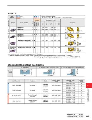
ApplicationInnerOuterPeripheral DC Class VP15TF VP20RT VP30RT DC W1W1 BSBS W1W1 DC INDEXABLE MILLING INSERTS Work P Steel Cutting Conditions (Guide) : Material K Cast Iron : Stable Cutting : General Cutting : Unstable Cutting Coated Dimensions (inch) Shape Order Number Geometry RE L W1 S BS *2 SRG40C G s s s .787 1.417 .807 .315 ─ *2 SRG50C G s s s .984 1.575 1.024 .335 ─ RE L S *2 SRG40E G s s s .787 1.260 .654 .315 ─ *2 SRG50E G s s s .984 1.409 .787 .335 ─ RE L S *1 APMT1604PDER-M2 M a .031 .650 .375 .187 .055 L RE AN 11° 85° .551 S Strong Cutting APMT1604PDER-H2 M a .031 .650 .375 .187 .055 L RE Edge Type AN 11° 85° .551 S (Low-resistance inner or outer inserts are precision M class type.) *1 Selection guide for peripheral cutting edges : The first recommendation is When cutting edge strength the super sharp M breaker (APMT....PDER-M2). is particularly important, use the H breaker (APMT....PDER-H2). RECOMMENDED CUTTING CONDITIONS A : Slot Milling B : Shoulder Milling (Standard Type) C : Shoulder Milling (Long Cutting Edge Type) Cutting Mode DC DC DC Work Material Hardness Grade Cutting Speed(SFM) Feed per Tooth Cutting(IPR)Mode P Alloy Tool Steel .008 (.004 ─ .012) A< 250HBVP20RTVP30RT655 (525 ─820).008 (.004 ─ .016)BL .012 (.004 ─ .016) C .008 (.004 ─ .012) A Cast Tool Steel < 230HB VP15TFVP20RT 655 (525 ─985) .012 (.004 ─ .018) B .008 (.004 ─ .016) C K Ductile Cast Iron .010 (.004 ─ .016) ATensile Strength< 540MPaVP15TFVP20RT655 (525 ─985).010 (.004 ─ .018)B.014 (.004 ─ .018)C .010 (.004 ─ .016) A Gray Cast Iron Tensile Strength< 350MPa VP15TFVP20RT 655 (525 ─985) .014 (.004 ─ .018) B.010 (.004 ─ .016)C SPARE PARTS N001 TECHNICAL DATA P001 L287