Общий каталог Mitsubishi 2020 - 2021 - страница 1410
Навигация
 Каталог Mitsubishi Materials запасные части
 Каталог Mitsubishi Materials резьбонарезной инструмент
 Каталог Mitsubishi Materials СНП с CBN и PCD для токарной обработки
 Каталог Mitsubishi Materials сверлильные инструменты
 Каталог Mitsubishi Materials расточной инструмент
 Каталог Mitsubishi Materials пластины для точения
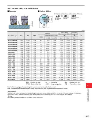
RMPX
X(inch)
DCX
INDEXABLE MILLING
MAXIMUM CAPACITIES BY MODE
y Ramping y Helical Milling
L a How to derive a locus of the center of the tool.
ødc = øDH - DCX
Locus of Desired Hole Cutting Diameter
the Center of Diameter Maximum
the Tool
ødc
øDH
( inch)
Ramping Helical Milling Helical Milling(Blind Hole, Flat Bottom)(Through Hole)
Tool Holder Type DCX DC APMX L (inch) Required Distance for X inch Depth DH DH AZ
RMPX
x = .039 x = .079 Min. Max. Min.
WJX14UR2.000 2.000 1.338 .079 4.3 .524 1.048 3.285 3.901 2.919 .082
WJX14UR2.500 2.500 1.887 .079 3° .752 1.503 4.283 4.901 3.912 .082
WJX14UR3.000 3.000 2.387 .079 2.2° 1.025 2.050 5.283 5.901 4.909 .082
WJX14UR4.000 4.000 3.386 .079 1.5° 1.504 3.007 7.282 7.901 6.906 .082
WJX14UR5.000 5.000 4.386 .079 1.1° 2.051 4.101 9.281 9.901 8.904 .082
WJX14UR6.000 6.000 5.386 .079 0.9° 2.507 5.013 11.281 11.901 10.903 .082
WJX14R50 1.969 1.358 .079 4.4° .512 1.024 3.228 3.819 2.874 .082
WJX14-050 1.969 1.358 .079 4.4 .512 1.024 3.228 3.819 2.874 .082
WJX14R050 1.969 1.358 .079 4.4 .512 1.024 3.228 3.819 2.874 .082
WJX14-052 2.047 1.437 .079 4.1 .551 1.102 3.386 3.976 3.031 .082
WJX14-063 2.480 1.870 .079 3° .752 1.504 4.252 4.843 3.898 .082
WJX14R063 2.480 1.870 .079 3° .752 1.504 4.252 4.843 3.898 .082
WJX14-066 2.598 1.984 .079 2.8° .807 1.610 4.488 5.079 4.134 .082
WJX14-080 3.150 2.535 .079 2.1° 1.075 2.150 5.591 6.181 5.236 .082
WJX14R080 3.150 2.535 .079 2.1° 1.075 2.150 5.591 6.181 5.236 .082
WJX14-100 3.937 3.323 .079 1.5° 1.504 3.008 7.165 7.756 6.811 .082
WJX14R100 3.937 3.323 .079 1.5° 1.504 3.008 7.165 7.756 6.811 .082
WJX14-125 4.921 4.307 .079 1.2° 1.882 3.760 9.134 9.724 8.780 .082
WJX14R125 4.921 4.307 .079 1.2° 1.882 3.760 9.134 9.724 8.780 .082
WJX14-160 6.299 5.685 .079 0.8° 2.823 5.642 11.890 12.480 11.535 .082
WJX14R160 6.299 5.685 .079 0.8° 2.823 5.642 11.890 12.480 11.535 .082
DCX = Cutting Dia. Max. DC = Cutting Dia. DH = Desired Hole Dia.
APMX = Depth of Cut Max. RMPX = Ramping Angle Max. AZ = Plunge Depth Max.
L
Note 1) When ramping and helical milling, it is recommended to reduce the feed per tooth.
Note 2) When ramping, helical milling and drilling, long continuous chips may be scattered so please be careful.