Общий каталог Mitsubishi 2020 - 2021 - страница 1246
Навигация
 Каталог Mitsubishi Materials запасные части
 Каталог Mitsubishi Materials резьбонарезной инструмент
 Каталог Mitsubishi Materials СНП с CBN и PCD для токарной обработки
 Каталог Mitsubishi Materials сверлильные инструменты
 Каталог Mitsubishi Materials расточной инструмент
 Каталог Mitsubishi Materials пластины для точения
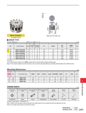
LCCB L8APMX *2 CBDP LF LCCB L8APMX CBDP LF LCCB INDEXABLE MILLING Fig.1 ø40 ø50 ø63 DCSFMS DCSFMSDCON DCSFMSDCONKWW DCON KWW KWW KAPR KAPR DAH DAH DAH DCCB DCCB DCCB DC DC DC Metric Standard Right hand tool holder only. For Metric Arbors y ARBOR TYPE DC = mm, DCON = mm GAMP : +5° GAMF: -6°─ -3° ( mm) *1 DC Order Number Stock CoolantThruNumberof TeethLF DCON WT(kg) RPMX(min-1) Fig. 40 FMAX-040A04R s Y 4 40 16 0.24 30000 1 40 FMAX-040A06R s Y 6 40 16 0.23 30000 1 50 FMAX-050A08R s Y 8 40 22 0.37 30000 1 50 FMAX-050A10R s Y 10 40 22 0.35 30000 1 63 FMAX-063A10R s Y 10 40 22 0.67 27000 1 63 FMAX-063A12R s Y 12 40 22 0.66 27000 1 1 Y=Yes *2 For the maximum depth of cut (APMX), please *Note 1) The maximum depth of cut for should be 2 refer to recommended cutting conditions (ap). mm or less for ultra high efficiency machining with table feed (vf ≥ 20000 mm/min). Mounting Dimensions ( mm) DCON DC Tool Holder Type CBDP DAH DCCB LCCB DCSFMS KWW L8 KWL Fig. 16 40 FMAX-040 18 9 14 10 37 8.4 5.6 ─ 1 22 50 FMAX-0502263FMAX-063 20 112011 17 12 47 10.4 6.317126010.46.3 ── 11 L SPARE PARTS ( mm) Insert Clamp * Micro Adjustment Large Adjustment Balance Adjustment Cutter Wrench Wrench Screw Nut Screw Screw Set Bolt T10 ø2.5 TSS04505S KSN2 KSS2 HSS04004G HSC10030H TKY10T RKY25S * Clamp Torque (lbf-in) : TSS04505S = Note 1) Refer to the instruction manual 31 included in the cutter body for how to locate the insert and adjust the run-out. Note 2) The cutter body includes a set bolt for an arbor. SPARE PARTS N001 TECHNICAL DATA P001 L071