Общий каталог Lamina Technologies 2019 - 2020 - страница 7
Навигация

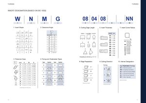
S SSS TURNING TURNING INSERT DESIGNATION (BASED ON ISO 1832) W N M G 08 04 08 NN 1 2 3 4 5 6 7 8 9 10 1. Insert Shape 2. Clearance Angle 5. Cutting Edge Length 6. Insert Thickness 7. Insert Corner Radius 85° 82° 80° 55° α° A, B, K C, D, E, M, V H, O, P Symbol mm A B C D Letter Symbol α 01 = 1.59 A 3° 55° B 5°GHKLC7°D15° T1 = 1.98LLL02=2.38 RLRS03=3.1800= Sharp corneror round insert 86° E 20° (inch version)T3=3.97M0 = Round insert F 25° (metric version) M O P R G 30° L L L 04 = 4.76 01 = 0.1 mm N 0°35° T W 05 = 5.56 02 = 0.2 mm04 = 0.4 mm 80° P 11° 06 = 6.35 08 = 0.8 mm S T V W O Special 07 = 7.94 12 = 1.2 mm16 = 1.6 mm L L 09 = 9.52 etc Disregarding any decimals e.g. 12,7 = 12 3. Tolerance Class 4. Fixing and Chipbreaker Types d (mm)m (mm) Symbol D M S Type Symbol Type Symbol 8. Edge Preparation 9. Cutting Direction 10. Internal Designation s (mm) A ± 0.025 ± 0.005 ± 0.025 A NmC± 0.025± 0.013± 0.025 Turning e.g. Chipbreaker (Turning) E ± 0.025 ± 0.025 ± 0.025 70°- 90° F NN = General purpose B PF± 0.013± 0.005± 0.025 R NM = Roughing operations m G ± 0.025 ± 0.025 ± 0.130 E NX = General purpose Magia F RØdH± 0.013± 0.013± 0.025 PP = All purpose grooving m J* ± 0.05-0.15 ± 0.005 ± 0.025 G 40°- 60°TK*± 0.05-0.15± 0.013± 0.025 T L NS = Non-ferrous materialsMP= Steel materials L* ± 0.05-0.15 ± 0.025 ± 0.025 70°- 90° 40°- 60°ØdHWM*± 0.05-0.15± 0.08-0.20± 0.130 S N Optional information N* ± 0.05-0.15 ± 0.08-0.20 ± 0.025 M X Special Design Optional information Optional information s U* ± 0.08-0.25 ± 0.13-0.38 ± 0.130 * Depending on the insert size. 10 11 Ød
 Общий каталог Lamina Technologies 2017 - 2018