Каталог Iscar сверла ружейные и для глубокого сверления 2022 - страница 122
Навигация
 Каталог Iscar новые продукты 2018
 Каталог Iscar полирующие фрезы
 Каталог Iscar инструмент для фрезерования
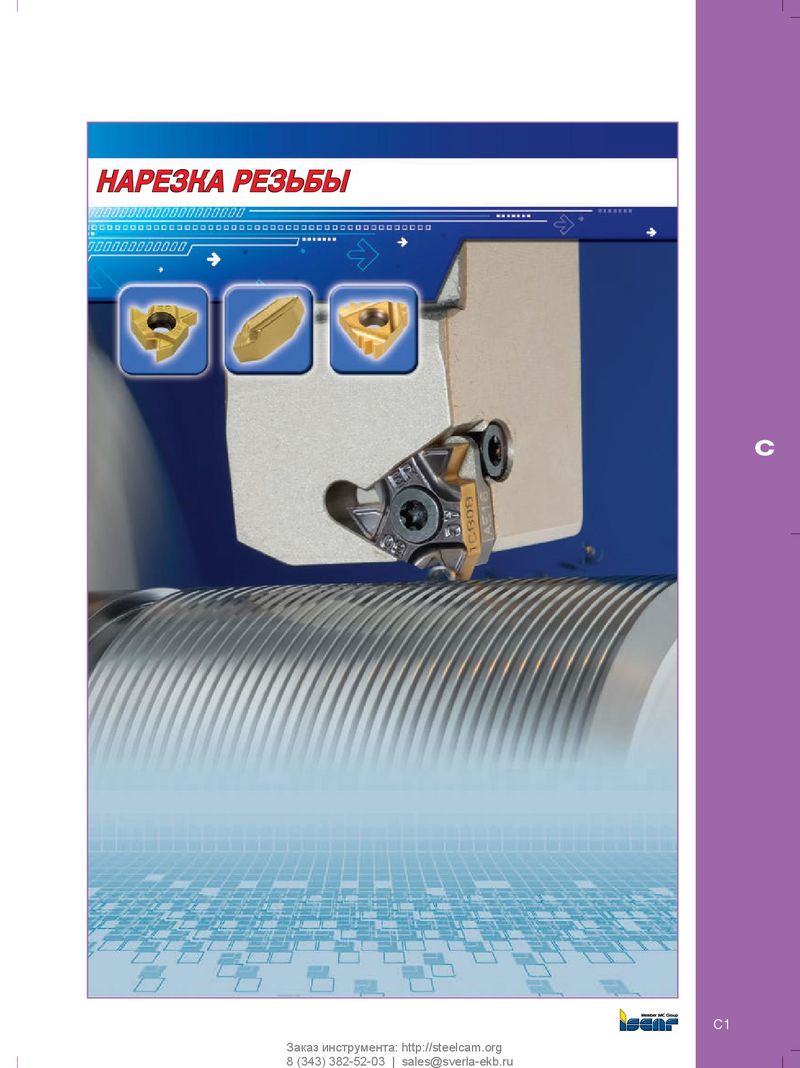 Каталог Iscar инструмент для нарезания резьбы
 Каталог Iscar токарные державки ISO 2022
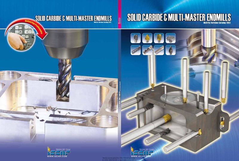 Каталог Iscar монолитные концевые фрезы и система multi-master
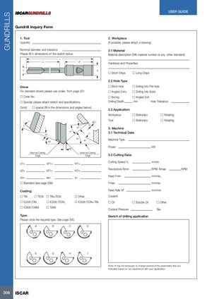
GUNDRILLS bF USER GUIDE Gundrill Inquiry Form 1. Tool 2. Workpiece Quantity (If possible, please attach a drawing) Nominal diameter and tolerance 2.1 Material Please fill in dimensions on the sketch below. Material description (DIN material number or any other standard): L Ls LA Hardness and Properties: D d o Short Chips o Long Chips 2.2 Hole Type Driver o Blind Hole o Drilling into Pre-hole For standard drivers please use codes from page 301 o Angled Entry o Drilling into Solid o Code No. o Boring o Angled Exit o Special, please attach sketch and specifications. Drilling Depth mm Hole Tolerance Grind: o special (fill in the dimensions and angles below). 2.3 Application: Workpiece: o Stationary o Rotating 1 Tool: o Stationary o Rotating γ αF1 3. Machine α1 3.1 Technical Data α2 ψ2 ψ1 α3 Machine Type. as Power kW Inter nal Cuttnig exter nal Cuttnig Edge Edge 3.2 Cutting Data: α1= αF1= Ψ1= Cutting Speed Vc m/min α2= bF1= Ψ2= Revolutions Nmin RPM, Nmax RPM α3= as= γ= Feed Fmin mm/rev, o Standard (see page 299) Fmax mm/rev Coating: Feed Rate VF mm/min o TiN o TiCN o TiN+TiCN o Other Coolant: o IC208 (TiN) o IC308 (TiCN) o IC508 (TiCN+TiN) o Oil o Soluble Oil o Other o IC908 (TiAlN) o TiAIN Coolant Pressure Bar Type: Sketch of drilling application Please circle the required type. See page 300. A B C D E G H I Note: It may be necessary to change several of the parameters that you indicated based on our experience with your application. 306 ISCAR