Каталог Iscar отрезка 2022 - страница 81
Навигация
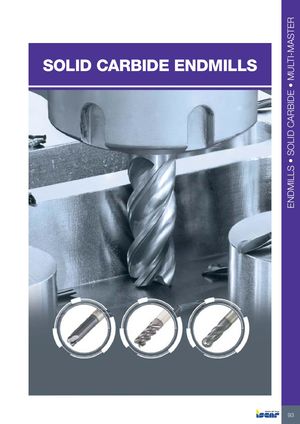 Каталог Iscar монолитные фрезы 2022
 Каталог Iscar резьбонарезные фрезы
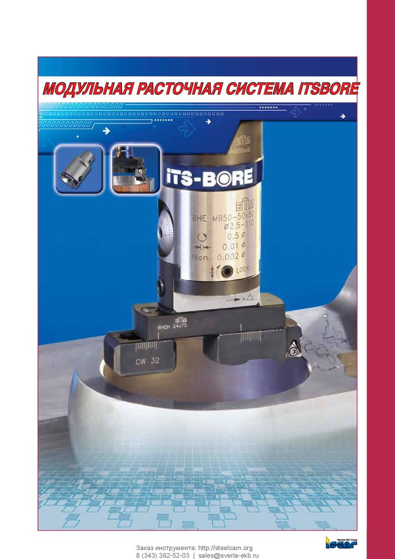 Каталог Iscar расточные системы
 Каталог Iscar токарный инструмент 2017
 Каталог Iscar инструмент для фрезерования
 Каталог Iscar высокоточные развертки и метчики 2022
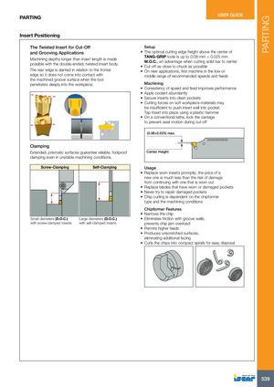
PARTING PARTING USER GUIDE Insert Positioning The Twisted Insert for Cut-Off Setup and Grooving Applications • The optimal cutting edge height above the center of Machining depths longer than insert length is madepossible with the double-ended, twisted insert body.TANG-GRIP tools is up to 0.08 mm + 0.025 mmW.O.C., an advantage when cutting solid bar to center•Cut-off as close tochuck as possible The rear edge is slanted in relation to the frontal • On new applications, first machine in the low or edge so it does not come into contact with middle range of recommended speeds and feeds the machined groove surface when the tool penetrates deeply into the workpiece. Machining • Consistency of speed and feed improves performance • Apply coolant abundantly • Secure inserts into clean pockets • Cutting forces on soft workpiece materials may be insufficient to push insert well into pocket. Tap insert into place using a plastic hammer • On a conventional lathe, lock the carriage to prevent axial motion during cut-off (0.08+0.025) max. Clamping Extended, prismatic surfaces guarantee reliable, foolproof Center Height clamping even in unstable machining conditions. Screw-Clamping Self-Clamping Usage • Replace worn inserts promptly, the price of a new one is much less than the risk of damage from continuing with one that is worn out • Replace blades that have worn or damaged pockets • Never try to repair damaged pockets • Chip curling is dependent on the chipformer type and the machining conditions Chipformer Features • Narrows the chip Small diameters (D.O.C.) Large diameters (D.O.C.) • Eliminates friction with groove walls, with screw-clamped Inserts with self-clamped Inserts prevents chip jam overload • Permits higher feeds • Produces unscratched surfaces, eliminating additional facing • Curls the chips into compact spirals for easy disposal 539