Каталог Iscar концевые фрезы со сменными пластинами 2022 - страница 37
Навигация
 Каталог Iscar токарный инструмент
 Каталог Iscar токарные пластины ISO 2022
 Каталог Iscar высокоточные развертки и метчики 2022
 Каталог Iscar крепление инструмента
 Каталог Iscar сверла ружейные и для глубокого сверления 2022
 Каталог Iscar инструментальная оснастка 2022
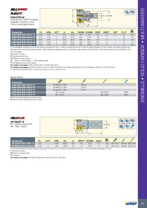
ENDMILLS • SOLID CARBIDE • MULTI-MASTER Rd° DC THSZMS DCONMS P290 EPW-M Endmills with FLEXFIT Threaded Adaptation Carrying 12 and DRVS 18 mm Long Edged Inserts APMX LF OAL Designation DC APMX CICT(1) LF OAL THSZMS DCONMS DRVS(2) RMPX°(3) CSP(4) TQ_3(5) kg P290 EPW D20-2-M10-12 20.00 12.00 2 25.00 45.00 M10 18.00 15.0 2.0 0 29 0.04 P290 EPW D25-3-M12-12 25.00 12.00 3 30.00 52.00 M12 21.00 19.0 1.4 1 33 0.07 P290 EPW D32-4-M16-12 32.00 12.00 4 35.00 60.00 M16 29.00 25.0 1.0 1 40 0.16 P290 EPW D32-3-M16-18 32.00 18.00 3 40.00 65.00 M16 29.00 25.0 2.0 1 40 0.15 P290 EPW D40-4-M16-18 40.00 18.00 4 40.00 65.00 M16 29.00 25.0 1.5 1 40 0.20 • For adaptation see page 44 • For user guide, see pages 542-548 • When mounting items with FLEXFIT threaded adaptation to their holders, the mating surfaces and threaded areas must be thoroughly cleaned. Apply appropriate tightening torque to eliminate a gap between the mating faces. Estimated torque values are specified in the TQ_3 parameter (1) Number of inserts (2) Clamping wrench size (3) Maximum ramping angle (4) 0 - Without coolant supply, 1 - With coolant supply (5) Tool tightening torque Nxm (lbfxin) For inserts, see pages: P290 ACCT/KT (461) • P290 ACKT (461) For holders, see pages: BT-ODP (FLEXFIT) (314) • C#-ODP (FLEXFIT) (314) • CAB M-M (FLEXFIT) (312) • DIN69871-ODP (315) • ER-ODP (315) • HSK A-ODP (FLEXFIT) (316) • S M (312) • S M-C-H (312) • S M-CF (313) Spare Parts Designation P290 EPW D20-2-M10-12 SR M3X0.5-L7.4 IP9(b) IP-9/151 P290 EPW D25-3-M12-12 SR M3X0.5-L7.4 IP9(b) IP-9/151 P290 EPW D32-4-M16-12 SR M3X0.5-L7.4 IP9(b) IP-9/151 P290 EPW D32-3-M16-18 SR 14-544/S(a) BLD T15/M7 SW6-T P290 EPW D40-4-M16-18 SR 14-544/S(a) BLD T15/M7 SW6-T (a) Recommended tightening torque:2.0 N*m (b) Recommended tightening torque:4.8 Nxm Rd° HP E90AT-19 90° Endmills Carrying HP DC DCONMS AD.. 1906.. Inserts APMX LU OAL Designation DC CICT(1) APMX OAL LU RMPX°(2) DCONMS Shank(3) kg HP E90AT-D25-2-W25-19 25.00 2 18.00 100.00 40.0 14.0 25.00 W 0.30 SR 14-571/L SW6-SD BLD T10/S7 HP E90AT-D32-3-W32-19 32.00 3 18.00 105.00 40.0 7.0 32.00 W 0.52 SR 14-571/L SW6-SD BLD T10/S7 • First loosely attach the inner clamping screw, then the outer one. In the same order tighten them both. • For user guide see pages 542-548 (1) Number of inserts (2) Maximum ramping angle (3) W-Weldon For inserts, see pages: HP ADCR 1906 (464) • HP ADKT/ADCT 1906 (464) 35