Общий каталог Ingersoll 2011 - страница 710
Навигация
 Общий каталог Ingersoll 2016 - 2017
 Общий каталог Ingersoll 2014
 Каталог Ingersoll инструмент для нарезания резьбы
 Общий каталог Ingersoll 2013 - 2014
 Каталог Ingersoll новинки 2021
- 0003 Table of Contents
- 0006 End Mills
- 0064 Long Edge
- 0104 0Deg Face Mills
- 0160 Face Mills
- 0202 Slotters
- 0218 Form Mills
- 0236 Profile Mills
- 0302 Milling Tech
- 0384 Solid Carbide
- 0448 Solid Carbide Tech
- 0474 Holemaking & Thread Milling
- 0666 Holemaking & Thread Milling Tech
- 0720 Innofit Top On Toolholders
- 0738 HSK Toolholders
- 0774 CAT Toolholders
- 0796 BT Toolholders
- 0816 Adaptions Accessories
- 0872 Turning Inserts
- 1024 Turning Holders
- 1144 Turning Tech
- 1174 Threading Inserts
- 1242 Threading Holders
- 1256 Threading Tech
- 1268 T-Clamp
- 1344 T-Clamp Tech
- 1376 T-CAP
- 1388 T-CAP Tech
- 1394 Product_Index
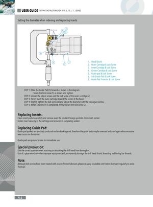
USER GUIDE SETTING INSTRUCTIONS FOR TBTA 3.../ 5.../ 7... SERIES Setting the diameter when indexing and replacing inserts Adjust screw 246 3 5 1 1. Head Shank 7 2. Outer Cartridge & Lock Screw 3. Inner Cartridge & Lock Screw 4. Center Cartridge & Lock Screw 5. Guide pad & Lock Screw 6. Sub Guide Pad & Lock Screw 7. Guide Pad Protector & Lock Screw STEP 1: Slide the Guide Pad (5) forward as shown in the diagram - locate the lock screw (5) as shown and tighten STEP 2: Loosen the adjust screws and the lock screw of the outer cartridge (2) STEP 3: Firmly push the outer cartridge toward the center of the head. STEP 4: Slightly tighten the lock screw (2) and adjust the diameter with the two adjust screws. STEP 5: When adjustment is completed, firmly tighten the lock screw (2). Replacing Inserts: Clean insert pockets carefully and remove even the smallest foreign particles from insert pocket. Fasten insert securely in the cartridge and ensure it is completely seated. Replacing Guide Pad: Guide pad pockets are precisely produced and are back tapered, therefore the guide pads may be reversed and used again when excessive wear occurs on the corner. Guide pads are ground to size for immediate use. Special precaution: Use the correct spanner when attaching or detaching the drill head from boring bar. Use of a pipe wrench or other improper equipment will permanently damage the drill head shank, threading and boring bar threads. Note: Although lock screws have been treated with an anti-friction lubricant, please re-apply a suitable anti-friction lubricant regularly to avoid “lock-up”. 712