Общий каталог Ingersoll 2011 - страница 676
Навигация
 Общий каталог Ingersoll 2016 - 2017
 Общий каталог Ingersoll 2014
 Каталог Ingersoll инструмент для нарезания резьбы
 Общий каталог Ingersoll 2013 - 2014
 Каталог Ingersoll новинки 2021
- 0003 Table of Contents
- 0006 End Mills
- 0064 Long Edge
- 0104 0Deg Face Mills
- 0160 Face Mills
- 0202 Slotters
- 0218 Form Mills
- 0236 Profile Mills
- 0302 Milling Tech
- 0384 Solid Carbide
- 0448 Solid Carbide Tech
- 0474 Holemaking & Thread Milling
- 0666 Holemaking & Thread Milling Tech
- 0720 Innofit Top On Toolholders
- 0738 HSK Toolholders
- 0774 CAT Toolholders
- 0796 BT Toolholders
- 0816 Adaptions Accessories
- 0872 Turning Inserts
- 1024 Turning Holders
- 1144 Turning Tech
- 1174 Threading Inserts
- 1242 Threading Holders
- 1256 Threading Tech
- 1268 T-Clamp
- 1344 T-Clamp Tech
- 1376 T-CAP
- 1388 T-CAP Tech
- 1394 Product_Index
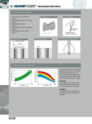
REPLACEABLE POINT DRILLS DRILL POINT REPLACEMENT INDICATIONS 1. Limit cutting edge wear to .008” to .012”. Fig. 1: Wear Limit Fig. 2: Power Restriction (see Fig. 1) 2. Power consumption exceeds 125% of normal. (1) (2) (see Fig. 2) P Px1.25 3. Drilled hole diameter variation. (see Fig. 3) 4. Deterioration of surface finish of the drilled hole. (see Fig. 4) Spindle loadmeter 5. Significant increase in noise or vibration. (see Fig. 5) .008"-.012" (1) New Drill Point(2) Worn Out Drill Point Fig. 3: Diameter Change Fig. 4: Surface Finish Decline Fig. 5: Noise or vibration drastically increases RECOMMENDED COOLANT PRESSURE AND FLOW RATE For proper chip evacuation, the coolant must flow through the tool. If the machine is not equipped with coolant through the spindle, we recom- mend using a coolant inducer. External coolant supply can be used if the hole depth is less than 1xD and reduced cutting parameters are applied. Coolant Mix Recommended coolant concentration is 6% to 8%. When drilling stainless and high strength steels, a 10% concentration is recommended. Dry Drilling It is possible to drill without coolant in cast iron. oil mist through the drill is required (2xD max hole depth). 678