Общий каталог Ingersoll 2011 - страница 458
Навигация
 Общий каталог Ingersoll 2016 - 2017
 Общий каталог Ingersoll 2014
 Каталог Ingersoll инструмент для нарезания резьбы
 Общий каталог Ingersoll 2013 - 2014
 Каталог Ingersoll новинки 2021
- 0003 Table of Contents
- 0006 End Mills
- 0064 Long Edge
- 0104 0Deg Face Mills
- 0160 Face Mills
- 0202 Slotters
- 0218 Form Mills
- 0236 Profile Mills
- 0302 Milling Tech
- 0384 Solid Carbide
- 0448 Solid Carbide Tech
- 0474 Holemaking & Thread Milling
- 0666 Holemaking & Thread Milling Tech
- 0720 Innofit Top On Toolholders
- 0738 HSK Toolholders
- 0774 CAT Toolholders
- 0796 BT Toolholders
- 0816 Adaptions Accessories
- 0872 Turning Inserts
- 1024 Turning Holders
- 1144 Turning Tech
- 1174 Threading Inserts
- 1242 Threading Holders
- 1256 Threading Tech
- 1268 T-Clamp
- 1344 T-Clamp Tech
- 1376 T-CAP
- 1388 T-CAP Tech
- 1394 Product_Index
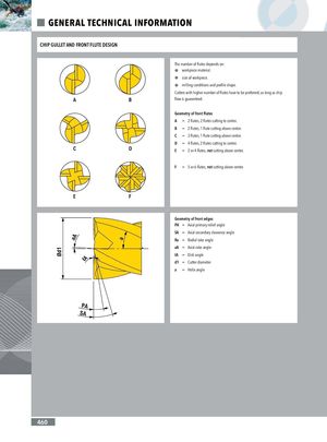
GENERAL TECHNICAL INFORMATION CHIP GULLET AND FRONT FLUTE DESIGN The number of flutes depends on: P workpiece material. P size of workpiece. P milling conditions and profile shape. Cutters with higher number of flutes have to be preferred, as long as chip flow is guaranteed. Geometry of front flutes A = 2 flutes, 2 flutes cutting to center. B = 2 flutes, 1 flute cutting above center. C = 3 flutes, 1 flute cutting above center. D = 4 flutes, 2 flutes cutting to center. E = 2 or 4 flutes, not cutting above center. F = 5 or 6 flutes, not cutting above center. Geometry of front edges PA = Axial primary relief angle SA = Axial secondary clearance angle Ra = Radial rake angle aA = Axial rake angle tA = Dish angle d1 = Cutter diameter a = Helix angle 460