Общий каталог Ingersoll 2011 - страница 1152
Навигация
 Общий каталог Ingersoll 2016 - 2017
 Общий каталог Ingersoll 2014
 Каталог Ingersoll инструмент для нарезания резьбы
 Общий каталог Ingersoll 2013 - 2014
 Каталог Ingersoll новинки 2021
- 0003 Table of Contents
- 0006 End Mills
- 0064 Long Edge
- 0104 0Deg Face Mills
- 0160 Face Mills
- 0202 Slotters
- 0218 Form Mills
- 0236 Profile Mills
- 0302 Milling Tech
- 0384 Solid Carbide
- 0448 Solid Carbide Tech
- 0474 Holemaking & Thread Milling
- 0666 Holemaking & Thread Milling Tech
- 0720 Innofit Top On Toolholders
- 0738 HSK Toolholders
- 0774 CAT Toolholders
- 0796 BT Toolholders
- 0816 Adaptions Accessories
- 0872 Turning Inserts
- 1024 Turning Holders
- 1144 Turning Tech
- 1174 Threading Inserts
- 1242 Threading Holders
- 1256 Threading Tech
- 1268 T-Clamp
- 1344 T-Clamp Tech
- 1376 T-CAP
- 1388 T-CAP Tech
- 1394 Product_Index
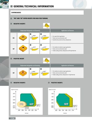
GENERAL TECHNICAL INFORMATION CHIPBREAKERS "WS" AND "WT" WIPER INSERTS FOR HIGH FEED TURNING NEGATIVE INSERTS Chipbreaker Designation and Geometry .0035” Application and Features 6° A B .0035” .0035” • For super finish applications WS 6° 6° • Steel, cast iron and stainless steel • Excellent chip control and low cutting forces .0035” 6° .0118” A B3° .0118” .0118” • For medium to medium rough applications WT 3° 0° • Steel, cast iron and stainless steel • Stable cutting and low cutting forces with high feed rate .0118” 0° POSITIVE INSERT Chipbreaker Designation and Geometry Application and Features .0035” A B0° .0035” .0047” • For medium to medium rough applications WT 0° 0° • Steel, cast iron and stainless steel • Stable cutting and low cutting forces in high feed rate .0047” 0° NEGATIVE INSERTS POSITIVE INSERTS Depth of cut (inch) Depth of cut (inch) .197 .120 .157 .100 .120 .080 .080 .060 .040 .040 .020 .028 .004 .008 .012 .016 .020 .024 .003 .005 .016 .008 .010 .016 Feed (ipr) Feed (ipr) 1154