Общий каталог FANAR 2021 - страница 11
Навигация
 Общий каталог FANAR 2018
 Каталог FANAR цельные твердосплавные фрезы
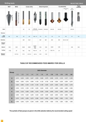
Multistage drill Drills to romove broken taps Drilling tools SELECTION TABLE WST WDG Center drills Deburring tools Countersinks Taperreamers Deburring tool with PF solid pilot Norm NC NC DIN-333 DIN-6537L DIN-6537L DIN-335 DIN-335 DIN-373 A / B / R / EL Tolerance Page number 165 166 167 167 168 - 171 172 172 174 174 176 177 178 Geometry δ90° δ120° δ60° δ90° δ90° δ90° δ30 / 45 / 60° External coolant HSSE / Material HSS VHM HSSE HSSE HSS / VHM VHM HSSE VHM HSS HSS VHM Coating - / TN2 AT TN2 TN2 TN2 / AT AT AT - / TN2 / TC AT - - - Range of 2,5÷10,2 3÷16 2,5÷10,2 0,8÷10 4÷20 4÷20 diameter TABLE OF RECOMMENDED FEED MM/REV FOR DRILLS Drill diameter Group Ć1 Ć2 Ć3 Ć4 Ć5 Ć6 Ć8 Ć10 Ć12 Ć14 Ć16 Ć20 a 0,015 0,030 0,038 0,047 0,053 0,060 0,075 0,090 0,100 0,120 0,127 0,160 b 0,020 0,050 0,070 0,085 0,100 0,120 0,150 0,180 0,200 0,230 0,250 0,270 c 0,023 0,080 0,100 0,130 0,150 0,180 0,250 0,270 0,280 0,300 0,330 0,370 d 0,030 0,100 0,160 0,180 0,220 0,240 0,300 0,370 0,400 0,450 0,480 0,500 e 0,035 0,120 0,200 0,250 0,270 0,300 0,350 0,450 0,470 0,500 0,530 0,550 f 0,050 0,150 0,220 0,250 0,320 0,400 0,490 0,620 0,650 0,720 0,850 0,900 g 0,070 0,160 0,250 0,270 0,360 0,470 0,620 0,830 0,900 0,950 1,100 1,200 h 0,090 0,200 0,270 0,300 0,400 0,520 0,750 1,000 1,100 1,200 1,300 1,350 The symbols of feed groups are given in the drills selection table by the recommended cutting speed 8